 W
WRobot kinematics applies geometry to the study of the movement of multi-degree of freedom kinematic chains that form the structure of robotic systems. The emphasis on geometry means that the links of the robot are modeled as rigid bodies and its joints are assumed to provide pure rotation or translation.
 W
W321 kinematic structure is a design method for robotic arms, invented by Donald L. Pieper and used in most commercially produced robotic arms. The inverse kinematics of serial manipulators with six revolute joints, and with three consecutive joints intersecting, can be solved in closed form, i.e. a set of equations can be written that give the joint positions required to place the end of the arm in a particular position and orientation. An arm design that does not follow these design rules typically requires an iterative algorithm to solve the inverse kinematics problem.
 W
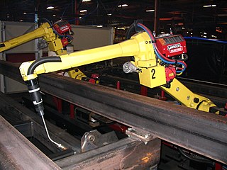
WAn articulated robot is a robot with rotary joints. Articulated robots can range from simple two-jointed structures to systems with 10 or more interacting joints and materials. They are powered by a variety of means, including electric motors.
 W
WA Cartesian coordinate robot is an industrial robot whose three principal axes of control are linear and are at right angles to each other. The three sliding joints correspond to moving the wrist up-down, in-out, back-forth. Among other advantages, this mechanical arrangement simplifies the Robot control arm solution. It has high reliability and precision when operating in three-dimensional space. As a robot coordinate system, it is also effective for horizontal travel and for stacking bins.
 W
WA Delta robot is a type of parallel robot that consists of three arms connected to universal joints at the base. The key design feature is the use of parallelograms in the arms, which maintains the orientation of the end effector, by contrast to Stewart platform that can change the orientation of its end effector.
 W
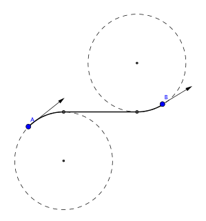
WIn geometry, the term Dubins path typically refers to the shortest curve that connects two points in the two-dimensional Euclidean plane with a constraint on the curvature of the path and with prescribed initial and terminal tangents to the path, and an assumption that the vehicle traveling the path can only travel forward. If the vehicle can also travel in reverse, then the path follows the Reeds–Shepp curve.
 W
WA five-bar linkage is a two degree-of-freedom mechanism that is constructed from five links that are connected together in a closed chain. All links are connected to each other by five joints in series forming a loop. One of the links is the ground or base. This configuration is also called a pantograph, however, it is not to be confused with the parallelogram copying linkage pantograph.
 W
WForward kinematics refers to the use of the kinematic equations of a robot to compute the position of the end-effector from specified values for the joint parameters.
 W
WA six-legged walking robot should not be confused with a Stewart platform, a kind of parallel manipulator used in robotics applications.
 W
WIn computer animation and robotics, inverse kinematics is the mathematical process of calculating the variable joint parameters needed to place the end of a kinematic chain, such as a robot manipulator or animation character's skeleton, in a given position and orientation relative to the start of the chain. Given joint parameters, the position and orientation of the chain's end, e.g. the hand of the character or robot, can typically be calculated directly using multiple applications of trigonometric formulas, a process known as forward kinematics. However, the reverse operation is, in general, much more challenging.
 W
WJansen's linkage is a planar leg mechanism designed by the kinetic sculptor Theo Jansen to generate a smooth walking motion. Jansen has used his mechanism in a variety of kinetic sculptures which are known as Strandbeesten. Jansen's linkage bears artistic as well as mechanical merit for its simulation of organic walking motion using a simple rotary input. These leg mechanisms have applications in mobile robotics and in gait analysis.
 W
WIn mechanical engineering, a kinematic chain is an assembly of rigid bodies connected by joints to provide constrained motion that is the mathematical model for a mechanical system. As in the familiar use of the word chain, the rigid bodies, or links, are constrained by their connections to other links. An example is the simple open chain formed by links connected in series, like the usual chain, which is the kinematic model for a typical robot manipulator.
 W
WThe Klann linkage is a planar mechanism designed to simulate the gait of legged animal and function as a wheel replacement, a leg mechanism. The linkage consists of the frame, a crank, two grounded rockers, and two couplers all connected by pivot joints. It was developed by Joe Klann in 1994 as an expansion of Burmester curves which are used to develop four-bar double-rocker linkages such as harbor crane booms. It is categorized as a modified Stephenson type III kinematic chain.
OMPL is a software package for computing motion plans using sampling-based algorithms. The content of the library is limited to motion planning algorithms, which means there is no environment specification, no collision detection or visualization. This is intentional as the library is designed to be easily integrated into systems that already provide the additional needed components. For example, OMPL is integrated with ROS and MoveIt!. In 2012 OMPL won the Grand Prize at the Open Source Software World Challenge.
 W
WA parallel manipulator is a mechanical system that uses several computer-controlled serial chains to support a single platform, or end-effector. Perhaps, the best known parallel manipulator is formed from six linear actuators that support a movable base for devices such as flight simulators. This device is called a Stewart platform or the Gough-Stewart platform in recognition of the engineers who first designed and used them.
 W
WSerial manipulators are the most common industrial robots and they are designed as a series of links connected by motor-actuated joints that extend from a base to an end-effector. Often they have an anthropomorphic arm structure described as having a "shoulder", an "elbow", and a "wrist".
 W
WSix degrees of freedom (6DOF) refers to the freedom of movement of a rigid body in three-dimensional space. Specifically, the body is free to change position as forward/backward (surge), up/down (heave), left/right (sway) translation in three perpendicular axes, combined with changes in orientation through rotation about three perpendicular axes, often termed yaw, pitch, and roll. Three degrees of freedom (3DOF), a term often used in the context of virtual reality, refers to tracking of rotational motion only: pitch, yaw, and roll.
 W
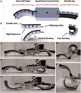
WSoft robotics is the specific subfield of robotics dealing with constructing robots from highly compliant materials, similar to those found in living organisms.
 W
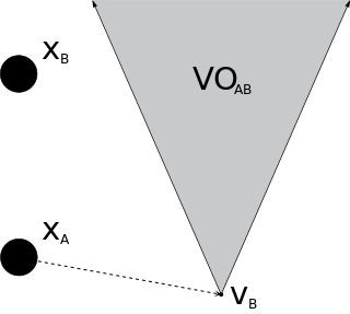
WIn robotics and motion planning, a velocity obstacle, commonly abbreviated VO, is the set of all velocities of a robot that will result in a collision with another robot at some moment in time, assuming that the other robot maintains its current velocity. If the robot chooses a velocity inside the velocity obstacle then the two robots will eventually collide, if it chooses a velocity outside the velocity obstacle, such a collision is guaranteed not to occur.